Free hotline:
86-755-88844016
+852 2632 9637
Image shown is a representation only.
Exact specifications should be obtained from the product data sheet.
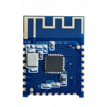
JDY-23 Bluetooth 5.0 module BLE5.0 Bluetooth transparent transmission Bluetooth data transmission CC2541 slave Bluetooth
JDY-23 Bluetooth 5.0 module BLE5.0 Bluetooth transparent module
JDY-23 Bluetooth 5.0 module BLE5.0 Bluetooth transparent transmission Bluetooth data transmission CC2541 slave Bluetooth
Product Descriptions:
Link: https://pan.baidu.com/s/1rSiDaG-h8I5NLjwzWiOJXw Extraction code: puj2
1、 Product Introduction
The JDY-23 transparent transmission module is based on the Bluetooth 5.0 protocol standard, with a working frequency range of 2.4GHz, modulation mode of GFSK, transmission power of 4db, and transmission distance of 60 meters. It is designed with imported original chips and supports users to modify device names, baud rates, and other commands through AT commands, making it convenient, fast, and flexible to use.
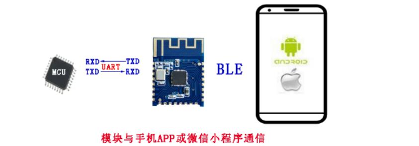
The JDY-23 Bluetooth module can achieve data transmission between the module and the mobile phone, and can quickly use BLE Bluetooth for product applications without configuration by default.
Make BLE more efficient and convenient in product applications
Module parameter details
3.1 Module Parameters
|
JDY-23 Product Parameters |
|
|
Model |
JDY-23 |
|
Working frequency band |
2.4G |
|
Transmission power |
4db() |
|
Communication interface |
UART |
|
working voltage |
1.8V – 3.6V |
|
working temperature |
-40℃ - 80℃ |
|
Antenna |
Built in PCB antenna |
|
Receiving sensitivity |
-97dbm |
|
Transmission distance |
60米 |
|
Master slave support |
From machine |
|
Module size |
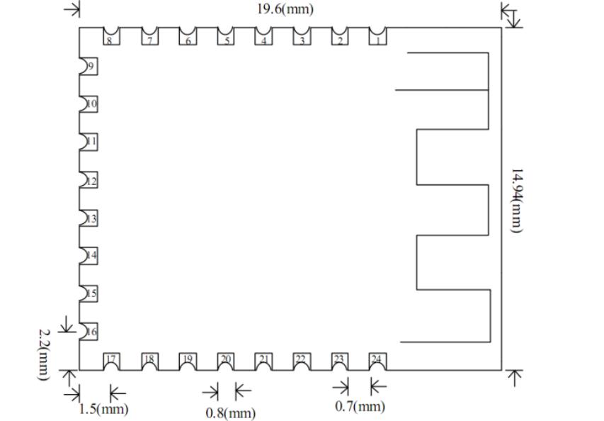
19.6 * 14.94 *1.8 mm(length, width, height) |
|
Bluetooth version |
BLE 5.0(compatible with BLE4.0 and BLE4.2) |
|
Wake up state current |
800uA(with broadcast) |
|
Shallow sleep state current |
<50uA (with broadcast) |
|
Deep sleep current |
9uA (no broadcast) |
|
SMT soldering temperature |
<260℃ |
|
Rf TX/RX peak current |
5mA |
Pin Definition
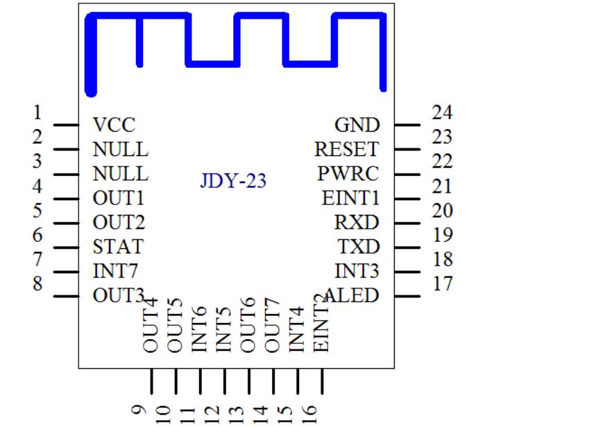
Pin Function Description
|
Pin |
Function |
Explain |
|
1 |
VCC |
Power supply (1.8-3.6V) |
|
2 |
NULL |
Empty |
|
3 |
NULL |
Empty |
|
4 |
OUTPUT1 |
IO1 output pin (supports APP control of high and low levels) |
|
5 |
OUTPUT2 |
IO2 output pin (supports APP control of high and low levels) |
|
6 |
STAT |
Connection status pin, connected to high level, not connected to low level |
|
7 |
INPUT7/PWM4 |
INPUT7 mode: It is an input pin, and the APP can read the status of this pin PWM mode: It is the output pin of PWM4, and the APP can control the pulse width of PWM4 Default: INPUT7 mode |
|
8 |
OUTPUT3 |
IO3 output pin (supports APP control of high and low levels) |
|
9 |
OUTPUT4 |
IO4 output pin (supports APP control of high and low levels) |
|
10 |
OUTPUT5 |
IO5 output pin (supports APP control of high and low levels) |
|
11 |
INPUT6/PWM3 |
INPUT6 mode: It is an input pin, and the APP can read the status of this pin PWM mode: It is the output pin of PWM3, and the APP can control the pulse width of PWM3 Default: INPUT6 mode |
|
12 |
INPUT5/PWM2 |
INPUT5 mode: It is an input pin, and the APP can read the status of this pin PWM mode: It is the output pin of PWM2, and the APP can control the pulse width of PWM2 Default: INPUT5 mode |
|
13 |
OUTPUT6 |
IO6 output pin (supports APP control of high and low levels) |
|
14 |
OUTPUT7 |
IO7 output pin (supports APP control of high and low levels) |
|
15 |
INPUT4 |
To input the pin, the APP can read the status of this pin |
|
16 |
EINT2 |
Interrupt input pin (press to actively send IO status to APP while connected) |
|
17 |
ALED |
Broadcast indicator pin |
|
18 |
INPUT3/PWM1 |
INPUT3 mode: It is an input pin, and the APP can read the status of this pin PWM mode: It is the output pin of PWM1, and the APP can control the pulse width of PWM1 Default: INPUT3 mode |
|
19 |
TXD |
Serial port output pin (TTL level) |
|
20 |
RXD |
Serial input pin (TTL level) |
|
21 |
EINT1 |
Interrupt input pin (press to actively send IO status to APP while connected) |
|
22 |
PWRC |
Sleep wake-up pin, low level effective In the connected state, the AT command can be sent by pulling down the PWRC pin |
|
23 |
RST |
Reset pin, low level effective |
|
24 |
GND |
Power Ground |
PCB packaging size
Serial port AT instruction set
The JDY-23 module serial port must include the AT command when sending it
|
Sequence |
Instructions |
Effect |
Master/From |
Default |
|
1 |
AT+VER |
Version number |
S |
JDY-23-V2.1 |
|
2 |
AT+RST |
Soft reset |
S |
- |
|
3 |
AT+DISC |
AT command to disconnect |
S |
- |
|
4 |
AT+STAT |
00 |
||
|
5 |
AT+MAC |
MAC address |
S |
- |
|
6 |
AT+BAUD |
Baud rate |
S |
9600 |
|
7 |
AT+SLEEP |
sleep |
S |
|
|
8 |
AT+NAME |
Broadcast Name |
S |
JDY-23 |
|
9 |
AT+STARTEN |
Power on sleep or wake-up |
S |
0(Power on wake-up) |
|
10 |
AT+ADVIN |
Broadcast interval |
S |
1(200mS) |
|
11 |
AT+HOSTEN |
From mode or IBEACON working mode |
S |
0(From the machine) |
|
12 |
AT+IBUUID |
The UUID of IBEACON |
S |
FDA50693A4E24FB1AFCFC6EB07647825 |
|
13 |
AT+MAJOR |
MAJOR from BEACON |
S Other Products In The same category:
1000In stock:
Can ship immediately
SEND |

