Free hotline:
86-755-88844016
+852 2632 9637
Image shown is a representation only.
Exact specifications should be obtained from the product data sheet.
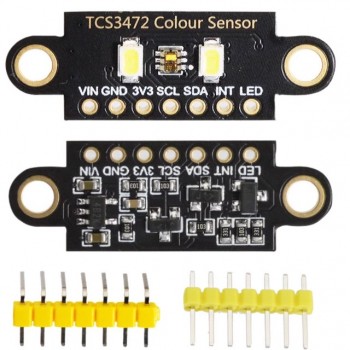
Hot selling TCS3472 color recognition sensor RGB development board IIC communication color recognition color sensing module
TCS3472 color recognition sensor IIC communication color recognition color sensing module
Product Introduction
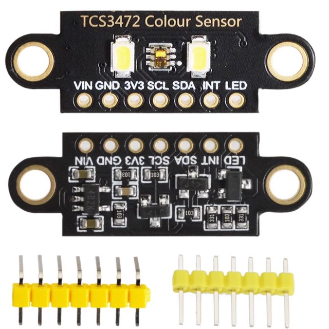
This module is a color sensor based on AMS TCS3472XFN color light digital converter as the core. The sensor provides digital outputs of red, green, blue (RGB) and clear light sensing values. Integrated infrared blocking filters can minimize the infrared spectral components of incident light and enable precise color measurement. Featuring high sensitivity, wide dynamic range, and infrared blocking filter. Minimize the effects of IR and UV spectral components to produce accurate color measurements. And it is equipped with environmental light intensity detection and shieldable interruption. Communicate through the 12C interface. This design is based on the same design principle and provides two different styling designs (square version/double hole version), providing users with more choices in installation size and environment. The double hole version is equipped with two LED lights to supplement the lighting of objects. This design provides Ardunio and SIM32 sample programs.
Product Parameter
Working voltage: 3.3V/5V
Control chip: TCS3472XFN
Logic voltage: 3.3V/5V
Communication interface: 12C
Product size
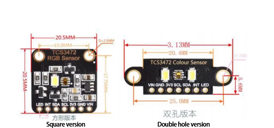
Interface Description
| Function pin | Description |
|---|---|
| VIN |
3.3V/5V power supply+ |
| GND | Power supply ground- |
| 3V3 | 3.3V |
| SCL | 12C clock input |
| SDA | 12C data input |
| INT | Interrupt output (open drain output) |
| LED | Light Emitting Diode |
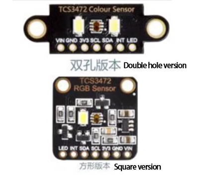
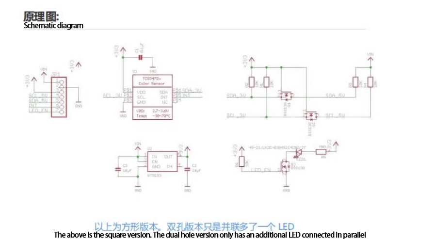
Communication protocol
I2C communication:
One data line, one clock line.
There are three types of signals in the I2C bus during data transmission: start signal, end signal, and response signal

Start signal: When SCL is at high level, SDA transitions from high level to low level and starts transmitting data
End signal: When SCL is at high level, SDA transitions from low level to high level, ending data transmission.
Response signal: After receiving 8-bit data, the IC receiving the data sends a specific low-level pulse to the IC sending the data, indicating that the I2C write timing has been received.
I2C write timing:

Firstly, the host will send a start signal, and then combine its 2C 7-bit address with the write operation bit to form 8-bit data and send it to the slave. After receiving it, the slave will respond with a response signal. The host will then send the command register address to the slave. When the slave receives the send response signal, the host will send the value of the command register, and the slave will respond with a response signal until the host sends a stop signal. This I2C write data operation ends.
I2C read timing:

Firstly, the host will send a start signal, and then combine its I2C 7-bit address with the write operation bit to form 8-bit data and send it to the slave. After receiving it, the slave will respond with a response signal. The host will then send the command register address to the slave. When the slave receives the send response signal, the host will resend a start signal and combine its 7-bit address with the read operation bit to form 8-bit data and send it to the slave. After receiving the signal, the slave will send a response signal, and then send the value in its register to the host. The host will give a response signal until it sends a stop signal. This communication ends.
I2C address:
The I2C device address is 0X29
Note: The device address 0X29 is 7 bits, and the 8-bit device address needs to be shifted one bit to the higher position 0X52.
Product Instructions
ARDUINO:
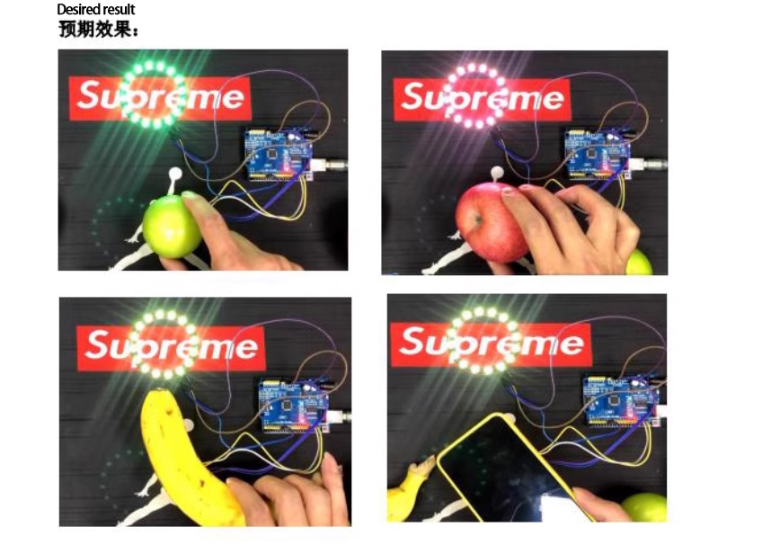
Download the routine and decompress it. The ARDUONUNO development board was used for testing, with a baud rate of 115200. Hardware connection:
| TCS3472X | Ardunio_UNO R3 |
|---|---|
| VIN | 5V |
| GND | GND |
| SCL | A5 |
| SDA | A4 |
|
WS2812 | Ardunio_UNO R3 |
|---|---|
| DIN | PIN6 |
| VCC | 5V |
| GND | GND |
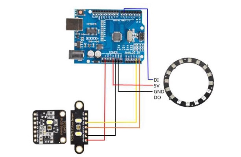
STM32:
下载例程解压,测试使用的是 STM32F103C8T6开发板,波特率为 115200,STM32开发板 USART1(PA9,PA10)通过串口模块连接电脑。硬件连接:
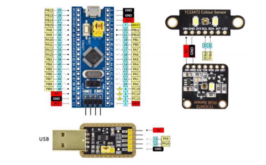
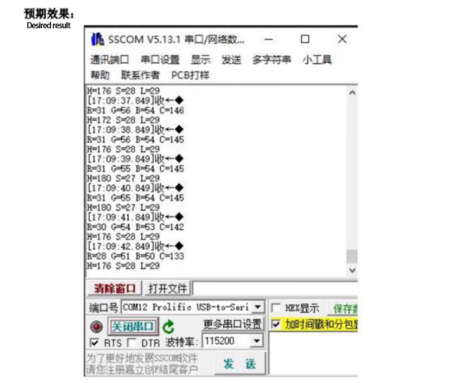
The download example is decompressed, and the test uses the STM32F103C8T6development board with a baud rate of 115200. The STM32 development boardUSART1 (PA9, PA10)is connected to the computer through the serial portmodule.
Hardware connection:
| TCS3472X | STM32 |
|---|---|
| VIN | 3.3V/5V |
| GND | GND |
| 3V3 | 3.3V |
| SCL | PB10 |
| SDA | PB11 |
| INT | XX |
| LED | 3.3V/5V |
Common problem
1. Is there no data or garbled data output in the serial port output of STM32 and Arduino routines?
Answer: Confirm if the baud rate is set to 115200. For the STM32 routine, please ensure that the computer is correctly connected to the development board USARTI (PA9, PA10), PA9 is TXD, and select the correct COM port. Control Panel ->Hardware ->Device Manager.
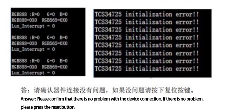
2. STM32 and Arduino routines output all RGB data as 0 or initialization fails?
3. The output RGB data is all 253 and the interrupt pin generates interrupts, etc
Answer: This situation is caused by the light intensity exceeding the inspection range, and reducing the gain can perfectly solve it.

4. Does modifying the points time result in abnormal color?
Answer: Because the integration time determines the maximum value of RGBC channel data, modifying the integration time will result in darker or whiter colors. Just increase or decrease the brightness of the LED.
5. Unable to trigger interruption or repeated interruption when modifying the points time?
Answer: Interruption is a comparison with the data in the Clear channel. The data in the Clear channel is related to the integration time. After actual measurement, the maximum value of the integration time channel is obtained with a gain of 60 times.
| Integral time | Maximum channel value |
|---|---|
| 2.4ms | 1024 |
| 24ms | 10240 |
| 50ms | 5400 |
| 101ms | 21504 |
| 154ms | 65535 |
| 700ms | 65535 |
So if users need to collect data quickly, they should pay attention to resetting the interrupt value. In addition, when the integration time is 2.4ms, the RGB data is relatively low, so the converted color deviates from the actual color. It is necessary to increase the brightness of the LED light.
Product Photograph
Payment&Transportation

Official Certificate&Certificate

Multiple product supply

Company office environment

Warehouse Real Shot
Standard packaging
We also provide :
| Part No | Manufacturer | Date Code | Quantity | Description |
| LM22676ADJ | NS | 19+ | 250 | SOP8 |
| TPS562201DDCR | TI | 22+ | 795500 | SOT23-6 |
| NJG1806K75 | JRC | 22+ | 500000 | DFN6 |
| TLV74318PDQNR | TI | 22+ | 402000 | X2SON-4 |
| NJG1801K75 | JRC | 22+ | 300000 | SMD |
| NJG1804K64 | JRC | 22+ | 300000 | DFN8 |
| LM27761DSGR | TI | 22+ | 151000 | WSON8 |
| TLV62565DBVR | TI | 22+ | 138000 | SOT23-5 |
| TPS613222ADBVR | TI | 22+ | 108000 | SOT23-5 |
| LNK625DG-TL | POWER | 22+ | 100000 | SOP-8 |
| OPA4322AIPWR | TI | 22+ | 100000 | TSSOP14 |
| TLV75528PDRVR | TI | 22+ | 99000 | WSON-6 |
| TPS7A2025PDQNR | TI | 22+ | 78500 | X2SON-4 |
| TLV62568DBVR | TI | 22+ | 72000 | SOT23-5 |
| STM32L051K8U6TR | ST | 22+ | 60000 | QFN32 |
| SKY66421-11 | SKYWORKS | 22+ | 56500 | QFN16 |
| TPS7A1111PDRVR | TI | 22+ | 54000 | WSON6 |
| TLV62569PDDCR | TI | 22+ | 52000 | SOT23-6 |
| TLV62569DBVR | TI | 22+ | 48000 | SOT23-5 |
| TPS23753APWR | TI | 22+ | 40000 | TSSOP14 |
| NB691GG-Z | MPS | 22+ | 30000 | QFN |
| SN74AHC1G02DBVR | TI | 22+ | 27939 | SOT-23 |
| TPS63000DRCR | TI | 22+ | 23238 | VSON10 |
| TLV75533PDRVR | TI | 22+ | 21500 | WSON6 |
| NB687BGQ-Z | MPS | 22+ | 20000 | QFN |
| A3916GESTR-T-1 | ALLEGRO | 22+ | 17150 | QFN-20 |
| TPS62135RGXR | TI | 22+ | 15000 | VQFN11 |
| TLE2022AMDR | TI | 0803+ | 12500 | SOP8 |
| TPS23756PWPR | TI | 22+ | 12000 | HTSSOP-20 |

