Image shown is a representation only.
Exact specifications should be obtained from the product data sheet.
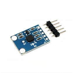
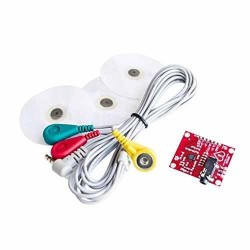
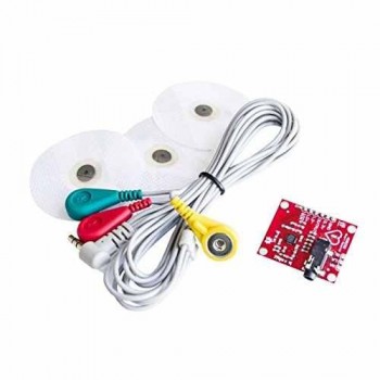
Ecg measurement Electrocardiogram module DIY kit AD8232
AD8232 Sensor module
Single lead heart rate monitor front end
The AD8232 is an integrated front-end for detecting cardiac bioelectrical signals
To monitor your heart rate.
An integrated signal conditioning module for ECG and other bioelectrical measurement applications. The device is designed to extract, amplify and filter weak bioelectrical signals in the presence of noise from moving or remote electrode placement. The design enables an ultra-low power analog-to-digital converter (ADC) or embedded microcontroller to easily capture the output signal.
The AD8232 uses a double-pole high-pass filter to eliminate moving artifacts and electrode half-cell potentials. The filter is closely coupled with the instrument amplifier structure, which can realize single-stage high-gain and high-pass filtering, thus saving space and cost.
The AD8232 uses a no-use constraint operational amplifier to create a three-pole low-pass filter, eliminating additional noise. Users can choose the cut-off frequency of all filters to meet the needs of different types of applications.
To improve common mode rejection of system line frequencies and other undesirable disturbances, the AD8232 has a built-in amplifier for driven lead applications such as right hand drive (RLD).
The AD8232 includes a fast recovery feature that reduces the long build tail of the high-pass filter. If there is a signal change in the amplifier rail voltage (such as lead disconnection), the AD8232 automatically adjusts to a higher filter cut-off state. This feature allows the AD8232 to achieve fast recovery so that a valid measurement value can be obtained as soon as possible after the lead is connected to the electrode of the measurement object.
The rated temperature range of guaranteed performance is 0 ° C to 70 ° C, and the operating temperature range is -40 ° C to +85 ° C.
Apply
Fitness and exercise heart rate monitoring
Portable ECG
Tele-health monitoring
Gaming peripherals
Bioelectrical signal acquisition
Pin Number Specifies the pin name
1 HPDRIVE Output of the high-pass drive. The HPDRIVE should be connected to the capacitor in the first high-pass filter.
The AD8232 drives this pin to keep the HPSENSE at the same level as the reference voltage.
2 +IN instrument amplifier positive input. +IN is usually attached to the left arm (LA) electrode.
3 −IN Negative input of the instrument amplifier. −IN is usually connected to the right arm (RA) electrode.
4 RLDFB right leg drive feedback input. RLDFB is the feedback pin of the right leg drive circuit.
5 RLD right leg driver output. The drive electrode (usually the right leg) should be connected to the RLD pin.
6 SW Quick recovery switch pin. This pin should be connected to the output of the second high-pass filter.
7 OPAMP+ operational amplifier in-phase input.
8 REFOUT Output end of the reference voltage buffer. The output of the instrumentation amplifier refers to this potential.
REFOUT should be used as a virtual ground for any point in the circuit where a reference signal is required.
9 OPAMP− OPAMP inverting input.
10 OUT The output of the operational amplifier. This output provides a fully conditioned heart rate signal.
The OUT can be connected to the input of the ADC.
11 LOD− Lead off output of the comparator. IN DC lead drop detection mode, when disconnected from the −IN electrode,
LOD− is in the high level state, and otherwise is in the low level state. In AC lead drop detection mode, LOD− is always low.
Lead off comparator output. IN DC lead drop detection mode, when the +IN electrode is disconnected, LOD+ is in a high level state.
Otherwise, it is in the low level state. IN AC lead drop detection mode, when the −IN or +IN electrode is disconnected, the LOD+ is in a high state.
When both electrodes are connected, they are at a low level.
12 LOD+
13 SDN Disables the control input. Drive the SDN to low level to enter low power shutdown mode.
14 AC/DC lead off mode Control input. For DC lead drop mode, the AC/DC pin should be driven to a low level.
For AC lead drop mode, the AC/DC pin should be driven to a high level.
15 FR Quick recovery control input. Driving FR to a high level enables fast recovery mode; Otherwise, drive it to a low level.
16 GND Power supply ground.
17 +VS power pin.
18 REFIN Input of the reference voltage buffer. REFIN(High impedance input pin) can be used to set the level of the reference voltage buffer.
19 IAOUT Instrument amplifier output pins.
20 High-pass detection input of HPSENSE instrumentation amplifier.
HPSENSE should be connected to the R and C nodes that set the turn frequency of the isolation circuit.
EP bare pad. Bare pads should be connected to GND or remain disconnected.


Ecg measurement Electrocardiogram module DIY kit AD8232
SEND
RFQ