Free hotline:
86-755-88844016
+852 2632 9637
Image shown is a representation only.
Exact specifications should be obtained from the product data sheet.
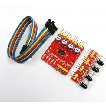
Hot selling spot 4-way infrared tracking/tracing module/line inspection module/obstacle avoidance/car/robot sensor
4-way infrared tracking/tracing module/line inspection module
Specification parameters
1. Working voltage: DC 3.3V-5V
2. Working current: Try to choose a power supply of 1A or above for power supply
3. Working temperature: - 10℃—+50℃
4. Installation aperture: M3 screw
5. Detection distance: adjustable from 1mm to 60 CM, the closer the distance, the more stable the performance, and the longer the white reflection distance.
6. Size: Central control board 44mm x 40mm x 12mm (length x width x height)
Small board 13.5mm x 12mm x 12mm (length x width x height)
7. Output interface: 6-wire system interface (1234 is the 4-channel signal output terminal,+is the positive power supply, - is the negative power supply, which is the ground wire)
8. Output signal: TTL level (can be directly connected to the microcontroller I/O signal. When the infrared light reflected back by the sensor is sensed, the red indicator light will light up and output a low level; when there is no infrared light, the indicator light will not light up and output a high level.)
Testing
Test probe: Move away all objects in front of the probe and do not point the probe in the direction of sunlight. Connect the probe board to the power supply and measure the output voltage with a multimeter. The voltage at this time should be around 1 volt. Cover the probe with white paper. The output voltage measured with a multimeter should be close to the power supply voltage. Testing the middle probe board: Connect the tested probe to the input terminal as indicated on the board, move away all objects in front of the probe, and do not point the probe in the direction of sunlight. Connect the middle probe board to the power supply and use a multimeter to measure the output terminal. At this time, the output voltage of the output terminal should be close to the power supply voltage. Cover the probe with white paper and measure the output voltage of the multimeter to be close to 0 volts. Adjust the potentiometer of the channel to change the detection distance.
Interface description
1. DO1--1-channel TTL level output
2. DO2-2-channel TTL level output
3. DO3--3-channel TTL level output
4. DO4-4-channel TTL level output
5. GND -- Connect to the negative pole of the power supply
6. VCC - Connect to the positive pole of the power supply
Adjustment
When the module detects an obstacle signal ahead, the green indicator light on the circuit board lights up at a certain level, and the OUT port continues to output a low-level signal. The module detects a distance of 2-30cm and a detection angle of 35 °. The detection distance can be adjusted through a potentiometer. Clockwise adjustment of the potentiometer increases the detection distance; Turn the potentiometer counterclockwise to reduce the detection distance.
Be careful:
1. When using this module, avoid direct sunlight on the probe. Light has an interference effect on modules
2. Sensitivity adjustment should not be too high, as excessive sensitivity may cause false triggering.
3. At the critical value, there will be a slight brightness of the LED, which is an untriggered state. At this time, the output is at a high level.
Application scope
1. Intelligent car or robot line finding (including black and white lines), walking along the black line path, also known as tracking.
2. Intelligent cars avoid cliffs and prevent falls.
3. Intelligent car obstacle avoidance
Shipping List
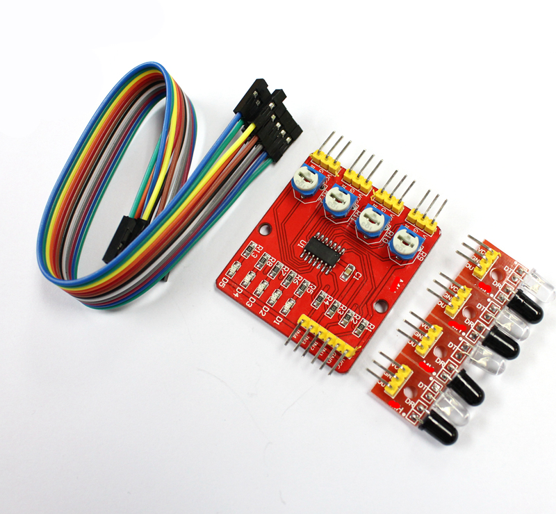
1 set of tracking module as shown in the figure (1 hollow board+4 small boards facing forward)
2.18 20cm DuPont wires for easy wiring
3. Provide the download address for the materials and download them yourself
Product real-life photos
Payment&Transportation

Official Certificate&Certificate

Multiple product supply

Company office environment

Warehouse Real Shot

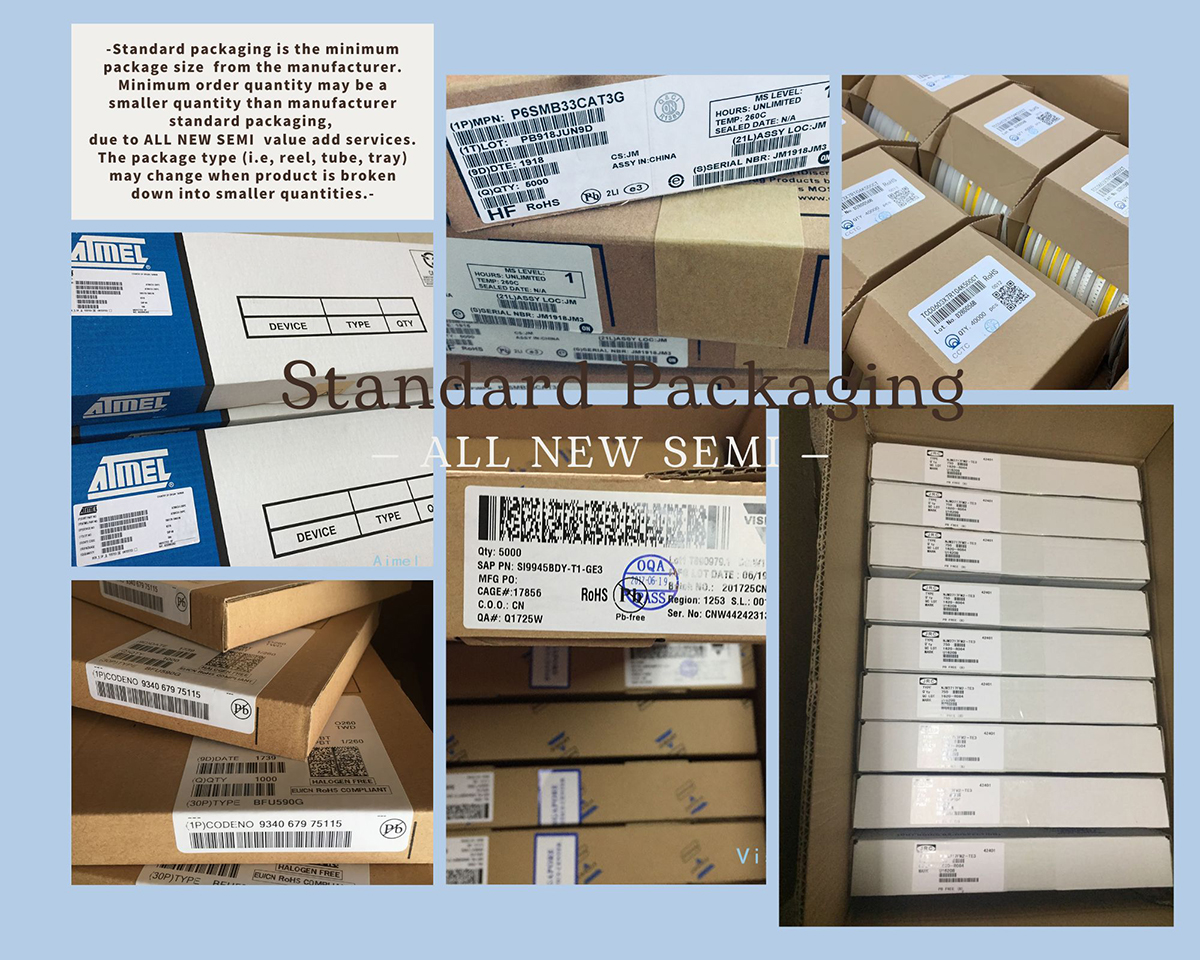
Standard packaging
We also provide :
| Part No | Manufacturer | Date Code | Quantity | Description |
| LM22676ADJ | NS | 19+ | 250 | SOP8 |
| TPS562201DDCR | TI | 22+ | 795500 | SOT23-6 |
| NJG1806K75 | JRC | 22+ | 500000 | DFN6 |
| TLV74318PDQNR | TI | 22+ | 402000 | X2SON-4 |
| NJG1801K75 | JRC | 22+ | 300000 | SMD |
| NJG1804K64 | JRC | 22+ | 300000 | DFN8 |
| LM27761DSGR | TI | 22+ | 151000 | WSON8 |
| TLV62565DBVR | TI | 22+ | 138000 | SOT23-5 |
| TPS613222ADBVR | TI | 22+ | 108000 | SOT23-5 |
| LNK625DG-TL | POWER | 22+ | 100000 | SOP-8 |
| OPA4322AIPWR | TI | 22+ | 100000 | TSSOP14 |
| TLV75528PDRVR | TI | 22+ | 99000 | WSON-6 |
| TPS7A2025PDQNR | TI | 22+ | 78500 | X2SON-4 |
| TLV62568DBVR | TI | 22+ | 72000 | SOT23-5 |
| STM32L051K8U6TR | ST | 22+ | 60000 | QFN32 |
| SKY66421-11 | SKYWORKS | 22+ | 56500 | QFN16 |
| TPS7A1111PDRVR | TI | 22+ | 54000 | WSON6 |
| TLV62569PDDCR | TI | 22+ | 52000 | SOT23-6 |
| TLV62569DBVR | TI | 22+ | 48000 | SOT23-5 |
| TPS23753APWR | TI | 22+ | 40000 | TSSOP14 |
| NB691GG-Z | MPS | 22+ | 30000 | QFN |
| SN74AHC1G02DBVR | TI | 22+ | 27939 | SOT-23 |
| TPS63000DRCR | TI | 22+ | 23238 | VSON10 |
| TLV75533PDRVR | TI | 22+ | 21500 | WSON6 |
| NB687BGQ-Z | MPS | 22+ | 20000 | QFN |
| A3916GESTR-T-1 | ALLEGRO | 22+ | 17150 | QFN-20 |
| TPS62135RGXR | TI | 22+ | 15000 | VQFN11 |
| TLE2022AMDR | TI | 0803+ | 12500 | SOP8 |
| TPS23756PWPR | TI | 22+ | 12000 | HTSSOP-20 |

