+86 135 5637 6665
+852 2632 9637
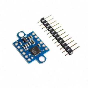
Image shown is a representation only.
Exact specifications should be obtained from the product data sheet.
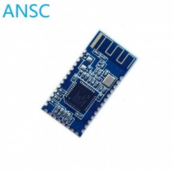
GY-53 VL53L0X Laser ToF time-of-Flight ranging sensor module Serial PWM output
Product Introduction
GY-53 is a low-cost digital infrared distance sensor module. The working voltage is 3-5v, the power consumption is low, and the size is small.
The working principle is that the infrared LED emits light, and after irradiating the measured object, the return light is received by the MCU, and the MCU calculates the time difference to get the distance and directly outputs the distance value. This module has two ways to read data, namely serial port UART (TTL level) + PWM (1 line) or chip IIC mode. The baud rate of the serial port is 9600bps and 115200bps, which can be configured. There are two modes of continuous and inquiry output, and the settings can be saved when the power is off. The module can also set the working mode of a separate sensor chip. As a simple sensor module, the MCU does not participate in data processing.
Pin Description
The module has 12 pins, two VCCs, two GNDs, TX pin is the serial port USART_TX, RX pin is the serial port USART_RX, PWM pin can convert distance into PWM output, SDA is the chip SDA pin, SCL is the chip SCL pin, PS pin is the serial port/IIC mode conversion pin, when ps=1 (default), serial port UART mode, Pin3 is TX, Pin4 is RX, TTL level, PWM output works; when ps=0 (connected to GND) IIC mode, users can operate the chip by themselves, the module's own MCU does not operate the chip, PWM output does not work.
Product Instructions
I use PWM mode, so here I will only introduce how to use PWM mode.
This distance measurement module is very similar to the ultrasonic module in PWM mode (it doesn't matter if you have never used the ultrasonic module). The programming idea is as follows:
When a high-level signal is received, turn on the timer to start timing, and turn off the timer after the signal ends. In this way, the high-level time is obtained. The chip inside the module will output a PWM wave with a period of 20HZ
. The high-level time corresponds to the measured distance (this is determined by the chip inside the module, we don't need to care about it), the formula is as follows:
* Distance (mm) = high-level time (ms) 100 = high-level time (us) / 10
For example: the measured high-level time is 10000us, then the distance = 10000/10 = 1000mm
|
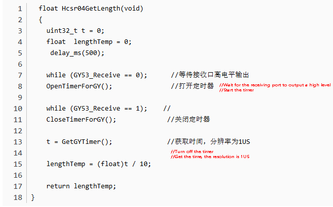
4. Code implementation The basic timer TIM6 used to obtain time is used for timing through interrupts. Then by calling this function a, the distance can be obtained: |
 |
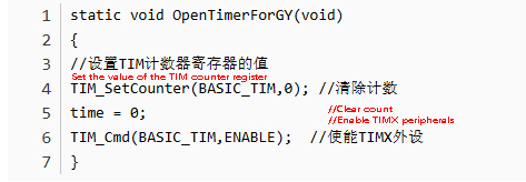
| Function to open the timer: |
 |
| Function to turn off the timer: |
 |
| Function to get time |
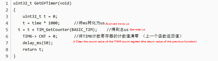 |
| 5. Result
Call the above function in the main function and print the obtained data through the serial port. The main function is as follows: |
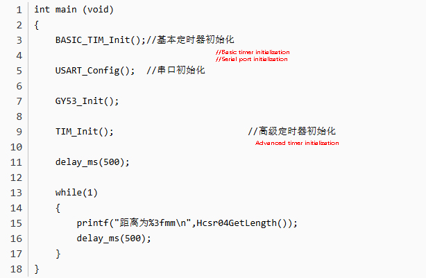 |
| The results are as follows |
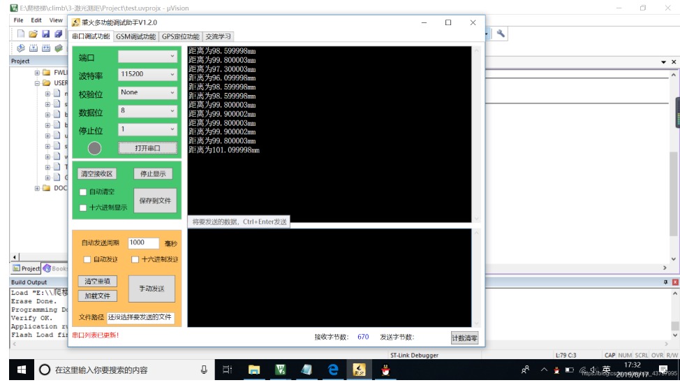 |
| Note: I found that if the inclination angle of this module changes during use, it will have a greater impact on the measured value, so when using it, try to make the module vertical to the horizontal plane in order to obtain a more accurate value. |
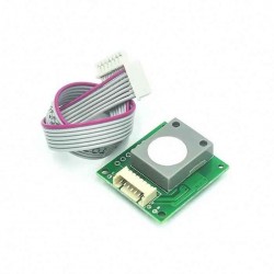
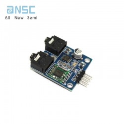
Actual image of the product
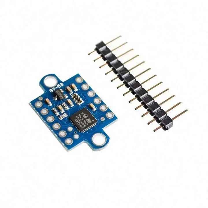
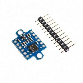
GY-53 VL53L0X Laser ToF time-of-Flight ranging sensor module Serial PWM output
SEND
RFQ