Power Management ICs
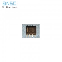
Hot-selling and scarce TLC7733IDR Micropower Supply Voltage Supervisors SOP8 spot stock
$0.22
+86 135 5637 6665
+852 2632 9637


Image shown is a representation only.
Exact specifications should be obtained from the product data sheet.
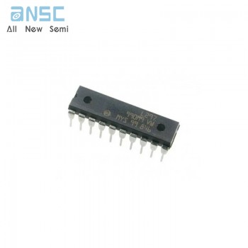
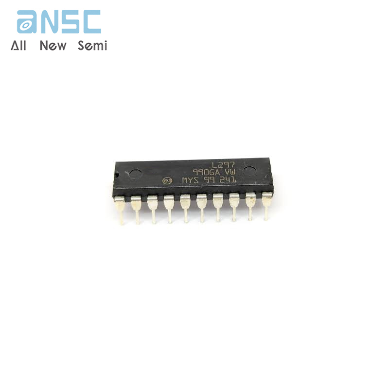
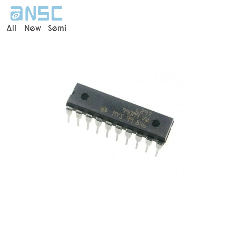
L297/1 STEPPER MOTOR CONTROLLERS DIP20 spot stock
The L297 Stepper Motor Controller IC generates four phase drive signals for two phase bipolar and four phase unipolar step motors in microcomputercontrolled applications.The motor can be driven in half step, normal and wawe drive modes and onchip PWM chopper circuits permit switch-mode control of the current in the windings.A feature of this device is that it requires only clock, direction and mode input signals.Since the phase are generated internally the burden on the microprocessor, and the programmer, is greatly reduced. Mounted in DIP20 and SO20 packages, the L297 can be used with monolithic bridge drives such as the L298N or L293E, or with discrete transistors and darlingtons.
NORMAL/WAVE DRIVE
HALF/FULL STEP MODES
CLOCKWISE/ANTICLOCKWISE DIRECTION
SWITCHMODE LOAD CURRENT REGULATION
PROGRAMMABLE LOAD CURRENT
FEW EXTERNAL COMPONENTS
RESET INPUT & HOME OUTPUT
ENABLE INPUT
| Attribute | Attribute value |
| ANSM-Part# | ANSM-L297/1 |
| Category | Integrated Circuits (ICs) |
| Power Management (PMIC) | |
| Motor Drivers, Controllers | |
| Manufacturer | - |
| Packaging | Tube |
| Part Status | Active |
| Motor Type - Stepper | Bipolar, Unipolar |
| Function | Controller - Commutation, Direction Management |
| Output Configuration | Pre-Driver - Half Bridge (4) |
| Interface | Parallel |
| Step Resolution | 1, 1/2 |
| Applications | General Purpose |
| Voltage - Supply | 4.75V ~ 7V |
| Operating Temperature | -40°C ~ 150°C (TJ) |
| Mounting Type | Through Hole |
| Package / Case | 20-DIP (0.300", 7.62mm) |
| Supplier Device Package | 20-DIP |
| Base Product Number | L297 |
For more product information, please download the PDF
WhenCE is HIGH (deselected),the device assumes a standby mode at which the power dissipation can be reduced down to250 µW (typical) with CMOS input levels.
L297/1 STEPPER MOTOR CONTROLLERS DIP20 spot stock
SEND
RFQ