
+86 135 5637 6665
+852 2632 9637
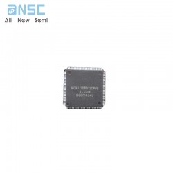
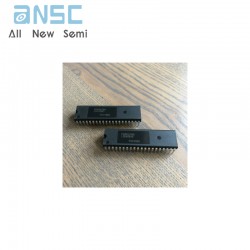
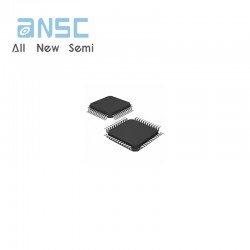
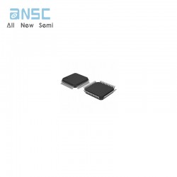
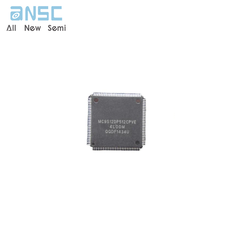
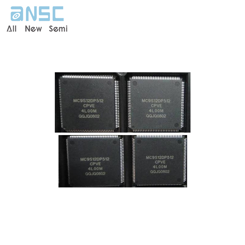
Image shown is a representation only.
Exact specifications should be obtained from the product data sheet.
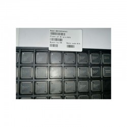
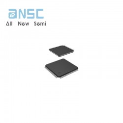
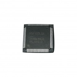
MC9S12DP512CPVE Microcontroller IC 16-Bit 25MHz 512KB FLASH 112-LQFP spot stock
The MC9S12DP512 microcontroller unit (MCU) is a 16-bit device composed of standard on-chip peripherals including a 16-bit central processing unit (HCS12 CPU), 512K bytes of Flash EEPROM, 14K bytes of RAM, 4K bytes of EEPROM, two asynchronous serial communications interfaces (SCI), three serial peripheral interfaces (SPI), an 8-channel IC/OC enhanced capture timer, two 8-channel, 10-bit analog-to-digital converters (ADC),an 8-channel pulse-width modulator (PWM),a digital Byte Data Link Controller (BDLC),29 discrete digital I/O channels (Port A,Port B,Port K and Port E),20 discrete digital I/O lines with interrupt and wake up capability, five CAN 2.0 A, B software compatible modules(MSCAN12), and an Inter-IC Bus. The MC9S12DP512 has full 16-bit data paths throughout. However, the external bus can operate in an 8-bit narrow mode so single 8-bit wide memory can be interfaced for lower cost systems. The inclusion of a PLL circuit allows power consumption and performance to be adjusted to suit operational requirements.
• HCS12 Core
– 16-bit HCS12 CPU
i. Upward compatible with M68HC11 instruction set
ii. Interrupt stacking and programmer’s model identical to M68HC11
iii.Instruction queue
iv.Enhanced indexed addressing
– MEBI (Multiplexed External Bus Interface)
– MMC (Module Mapping Control)
– INT (Interrupt control)
– BKP (Breakpoints)
– BDM (Background Debug Mode)
• CRG (Clock and Reset Generation)
– Low current Colpitts oscillator or
– Pierce oscillator
– PLL
– COP watchdog
– Real Time Interrupt
– Clock Monitor
• 8-bit and 4-bit ports with interrupt functionality
– Digital filtering
– Programmable rising or falling edge trigger
• Memory
– 512K Flash EEPROM
– 4K byte EEPROM
– 14K byte RAM
• Two 8-channel Analog-to-Digital Converters
– 10-bit resolution
– External conversion trigger capability
• Five 1M bit per second, CAN 2.0 A, B software compatible modules
– Five receive and three transmit buffers
– Flexible identifier filter programmable as 2 x 32 bit, 4 x 16 bit or 8 x 8 bit
– Four separate interrupt channels for Rx, Tx, error and wake-up
– Low-pass filter wake-up function
– Loop-back for self test operation
• Enhanced Capture Timer
– 16-bit main counter with 7-bit prescaler
– 8 programmable input capture or output compare channels
– Four 8-bit or two 16-bit pulse accumulators
• 8 PWM channels
– Programmable period and duty cycle
– 8-bit 8-channel or 16-bit 4-channel
– Separate control for each pulse width and duty cycle
– Center-aligned or left-aligned outputs
– Programmable clock select logic with a wide range of frequencies
– Fast emergency shutdown input
– Usable as interrupt inputs
• Serial interfaces
– Two asynchronous Serial Communications Interfaces (SCI)
– Three Synchronous Serial Peripheral Interface (SPI)
• Byte Data Link Controller (BDLC)
– SAE J1850 Class B Data Communications Network Interface Compatible and ISO Compatible for Low-Speed (<125 Kbps) Serial Data Communications in Automotive Applications
| Attribute | Attribute value |
| ANSM-Part# | ANSM-MC9S12DP512CPVE |
| Category | Integrated Circuits (ICs) |
| Embedded | |
| Microcontrollers | |
| Mfr | - |
| Series | HCS12 |
| Packaging | Tray |
| Part Status | Active |
| DigiKey Programmable | Verified |
| Core Processor | HCS12 |
| Core Size | 16-Bit |
| Speed | 25MHz |
| Connectivity | CANbus, I2C, SCI, SPI |
| Peripherals | PWM, WDT |
| Number of I/O | 91 |
| Program Memory Size | 512KB (512K x 8) |
| Program Memory Type | FLASH |
| EEPROM Size | 4K x 8 |
| RAM Size | 12K x 8 |
| Voltage - Supply (Vcc/Vdd) | 2.35V ~ 5.25V |
| Data Converters | A/D 16x10b |
| Oscillator Type | Internal |
| Operating Temperature | -40°C ~ 85°C (TA) |
| Mounting Type | Surface Mount |
| Supplier Device Package | 112-LQFP (20x20) |
| Package / Case | 112-LQFP |
| Base Product Number | MC9S12 |
For more product information, please download the PDF
WhenCE is HIGH (deselected),the device assumes a standby mode at which the power dissipation can be reduced down to250 µW (typical) with CMOS input levels.
MC9S12DP512CPVE Microcontroller IC 16-Bit 25MHz 512KB FLASH 112-LQFP spot stock
SEND
RFQ