+86 135 5637 6665
+852 2632 9637
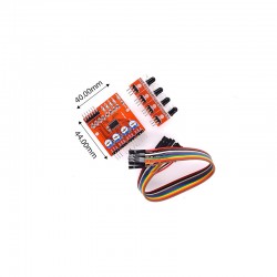
Image shown is a representation only.
Exact specifications should be obtained from the product data sheet.
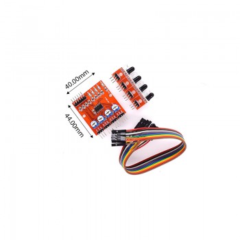
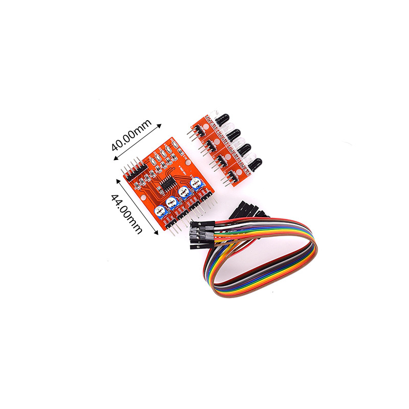
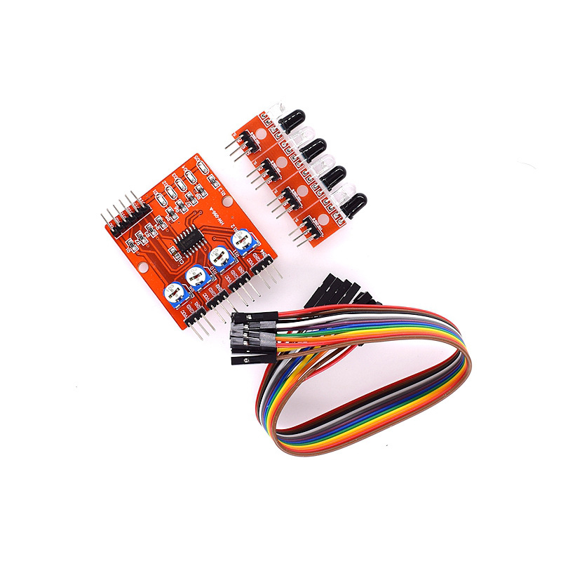
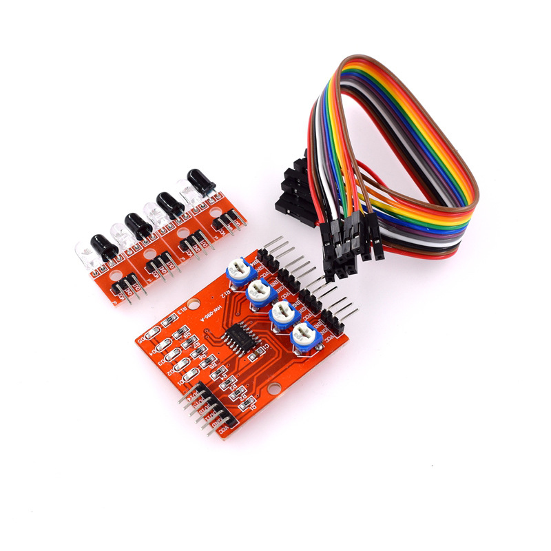
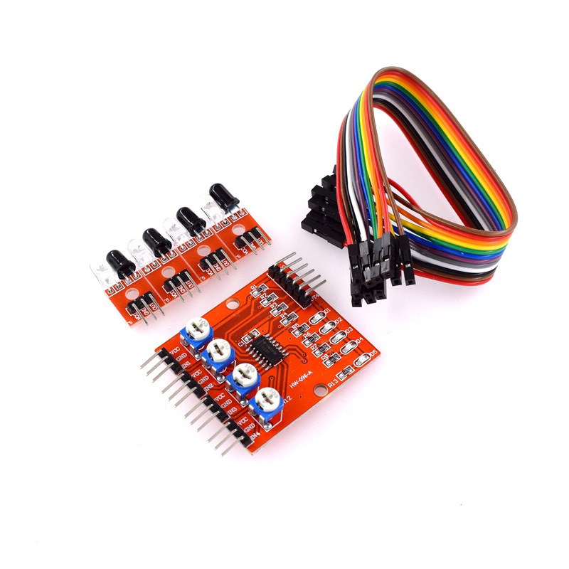
4-channel infrared tracking/tracing module/line inspection module
This module provides a versatile infrared detection system solution for automated mechanical devices such as smart cars and robots. This sensor module has strong adaptability to environmental light and has a pair of infrared emission and reception tubes. The emission tube emits infrared radiation at a certain frequency. When the detection direction encounters an obstacle (reflection surface), the infrared radiation is reflected back and received by the reception tube. After being processed by a comparator circuit, the signal output interface outputs a digital signal (a low-level signal). The detection distance can be adjusted through a potentiometer knob, with an effective distance range of 2-60cm and a working voltage of 3.3V-5V. The detection distance of this sensor can be adjusted by a potentiometer, and it has the characteristics of low interference, easy assembly, and convenient use. It can be widely used in many occasions such as robot obstacle avoidance, obstacle avoidance carts, assembly line counting, and black and white line tracking.
When the module detects an obstacle signal ahead, the red indicator light on the circuit board lights up, and the 0UT port continues to output a low-level signal. The module detects a distance of 2~60cm and a detection angle of 35 °. The detection distance can be adjusted through a potentiometer. Clockwise adjustment of the potentiometer increases the detection distance; Turn the potentiometer counterclockwise to reduce the detection distance.
The sensor belongs to infrared reflection detection, so the reflectivity and shape of the target are the key to the detection distance. Among them, black has the smallest detection distance and white has the largest; Small objects have smaller distances, while large objects have larger distances.
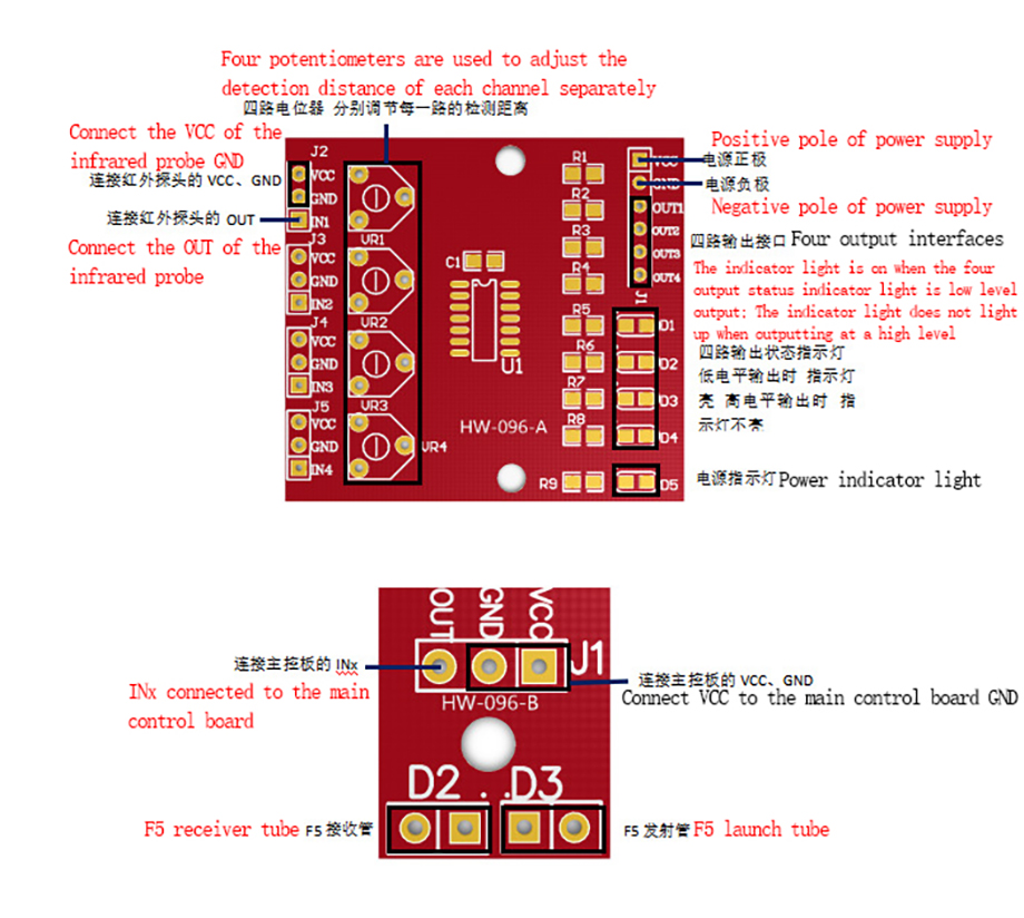
The output port OUT of the sensor module can be directly connected to the 10 port microcontroller, or it can directly drive a 5V relay module or buzzer module; Connection method: VCC-VCC; GND-GND; OUT-I0
The comparator adopts LM339, which works stably;
The module can be powered by a 3.3V-5V DC power supply. When the power is turned on, the red power indicator light is on;
The infrared probe VCC GND OUT is connected to the central control board VCC GND INx
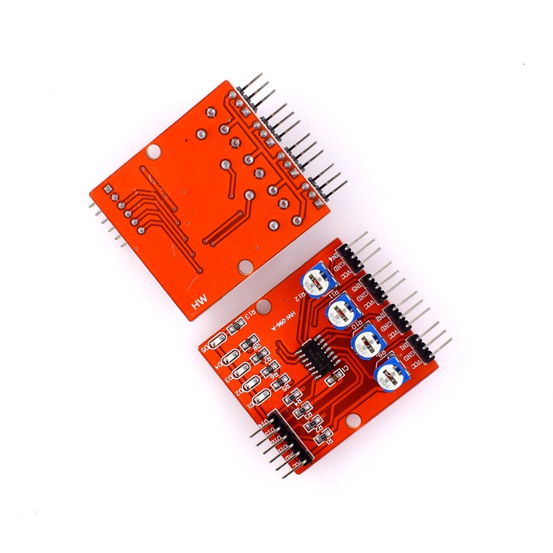
Central control board power supply: VCC external voltage of 3.3V-5V is connected to the 6P pin interface of module (can be directly connected to 5V microcontroller and 3.3V microcontroller); GND external connection GND; OUT1-OUT4 connected to microcontroller IO port
Output signal: TTL level (can be directly connected to the microcontroller I/O port. When the infrared light reflected back by the sensor is sensed, the corresponding red indicator light will light up and output a low level; when there is no infrared light reflected back, the indicator light will not light up and output a high level (high level is equal to the power supply voltage)
Test probe: Move away all objects in front of the probe, and do not point the probe towards a place with sunlight (light can cause significant interference to the probe). Connect the probe board to the power supply and use a multimeter to measure the voltage between OUT and GND. The normal range should be between 0.6V-2.5V. Cover the probe with a paper and use a multimeter to measure the voltage between OUT and GND. The normal range should be close to 0V. Simply put, after covering the probe with white paper, there will be a significant decrease in voltage between OUT and GND, which is considered normal.
Testing the central control board separately: This requires first understanding the working principle of LM339. Let's briefly explain the first circuit: IN1- is the voltage input terminal for the locator adjustment, IN1+is the voltage output by the probe (i.e. the voltage between the probe OUT and GND). When the IN1- voltage is greater than the IN1+voltage, the corresponding output voltage of OUT1 is close to 0V, and at this time, the corresponding LED light will be high; When IN1 voltage is less than IN1+voltage, the corresponding output voltage of OUT1 is close to 5V, and the corresponding LED light will light up. This is the core of the entire circuit operation.
Based on this principle, we can conduct a simple test by adjusting the potentiometer of the first circuit to make the voltage of IN - around 2.5V. Then, according to the above principle, connect IN1 to 0V and 5V voltages respectively. Based on the above principle, we will find that when OV is connected, the LED light will light up; When connected to 5V, the LED light goes out.
Online testing: Connect the probe to the central control board according to the requirements, move away all objects in front of the probe, and do not point the probe to a place with sunlight (light can cause significant interference to the probe). Adjust the potentiometer of each circuit until the light just goes out, and then cover it with white paper.



We also provide :
| Part No | Manufacturer | Date Code | Quantity | Description |
| LM22676ADJ | NS | 19+ | 250 | SOP8 |
| TPS562201DDCR | TI | 22+ | 795500 | SOT23-6 |
| NJG1806K75 | JRC | 22+ | 500000 | DFN6 |
| TLV74318PDQNR | TI | 22+ | 402000 | X2SON-4 |
| NJG1801K75 | JRC | 22+ | 300000 | SMD |
| NJG1804K64 | JRC | 22+ | 300000 | DFN8 |
| LM27761DSGR | TI | 22+ | 151000 | WSON8 |
| TLV62565DBVR | TI | 22+ | 138000 | SOT23-5 |
| TPS613222ADBVR | TI | 22+ | 108000 | SOT23-5 |
| LNK625DG-TL | POWER | 22+ | 100000 | SOP-8 |
| OPA4322AIPWR | TI | 22+ | 100000 | TSSOP14 |
| TLV75528PDRVR | TI | 22+ | 99000 | WSON-6 |
| TPS7A2025PDQNR | TI | 22+ | 78500 | X2SON-4 |
| TLV62568DBVR | TI | 22+ | 72000 | SOT23-5 |
| STM32L051K8U6TR | ST | 22+ | 60000 | QFN32 |
| SKY66421-11 | SKYWORKS | 22+ | 56500 | QFN16 |
| TPS7A1111PDRVR | TI | 22+ | 54000 | WSON6 |
| TLV62569PDDCR | TI | 22+ | 52000 | SOT23-6 |
| TLV62569DBVR | TI | 22+ | 48000 | SOT23-5 |
| TPS23753APWR | TI | 22+ | 40000 | TSSOP14 |
| NB691GG-Z | MPS | 22+ | 30000 | QFN |
| SN74AHC1G02DBVR | TI | 22+ | 27939 | SOT-23 |
| TPS63000DRCR | TI | 22+ | 23238 | VSON10 |
| TLV75533PDRVR | TI | 22+ | 21500 | WSON6 |
| NB687BGQ-Z | MPS | 22+ | 20000 | QFN |
| A3916GESTR-T-1 | ALLEGRO | 22+ | 17150 | QFN-20 |
| TPS62135RGXR | TI | 22+ | 15000 | VQFN11 |
| TLE2022AMDR | TI | 0803+ | 12500 | SOP8 |
| TPS23756PWPR | TI | 22+ | 12000 | HTSSOP-20 |
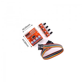
4-channel infrared tracking/tracing module/line inspection module
SEND
RFQ