+86 135 5637 6665
+852 2632 9637
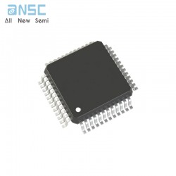
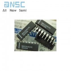
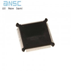
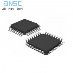
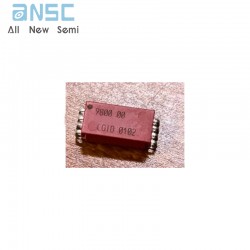
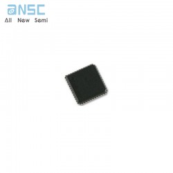
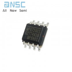
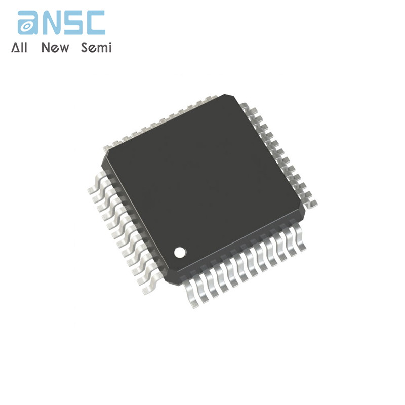
Image shown is a representation only.
Exact specifications should be obtained from the product data sheet.
MAX1324ECM+ 14-Bit, Simultaneous-Sampling ADCs
The MAX1316–MAX1318/MAX1320–MAX1322/MAX1324– MAX1326 14-bit, analog-to-digital converters (ADCs) offer two, four, or eight independent input channels. Independent track/hold (T/H) circuitry provides simultaneo us sampling for each channel. The MAX1316/ MAX1317/MAX1318 have a 0 to +5V input range with±6 .0V fault-tolerant inputs. The MAX1320/MAX1321/ MAX1322 have a ±5V input range with ±16 .5V fault-tolerant inputs. The MAX1324/MAX1325/MAX1326 have a±10V input range with ±16 .5V fault-tolerant inputs. These ADCs convert two channels in 2µs, and up to eight channels in 3.8µs, and have an 8-channel throughput of250ksps per channel. Other features include a 10MHz T/H input bandwidth, internal clock, internal (+2 .5V) or external (+2 .0V to +3 .0V) reference, and powersaving modes.
A 16.6MHz, 14-bit, bidirectional, parallel interface provides the conversion results and accepts digital configuration inputs.
These devices operate from a +4 .75V to +5 .25V analog supply and a separate +2 .7V to +5 .25V digital supply, and consume less than 50mA total supply current.
These devices come in a 48-pin LQFP package and operate over the extended -40°C to +85°C temperature range.
♦ 8-/4-/2-Channel, 14-Bit ADCs
±1.5 LSB INL, ±1 LSB DNL, No Missing Codes
90dBc SFDR, -86dBc THD, 76.5dB SINAD, 77dB
SNR at 100kHz Input
♦ On-Chip T/H Circuit for Each Channel
10ns Aperture Delay
50ps Channel-to-Channel T/H Matching
♦ Fast Conversion Time
One Channel in 1.6µs
Two Channels in 1.9µs
Four Channels in 2.5µs
Eight Channels in 3.7µs
♦ High Throughput
526ksps/ch for One Channel
455ksps/ch for Two Channels
357ksps/ch for Four Channels
250ksps/ch for Eight Channels
♦ Flexible Input Ranges
0 to +5V (MAX1316/MAX1317/MAX1318)
±5V (MAX1320/MAX1321/MAX1322)
±10V (MAX1324/MAX1325/MAX1326)
♦ No Calibration Needed
♦ 14-Bit, High-Speed, Parallel Interface
♦ Internal or External Clock
♦ +2 .5V Internal Reference or +2 .0V to +3 .0V External Reference
♦ +5V Analog Supply, +3V to +5V Digital Supply
46mA Analog Supply Current (typ)
1.6mA Digital Supply Current (max)
Shutdown and Power-Saving Modes
♦ 48-Pin LQFP Package (7mm x 7mm Footprint)
Multiphase Motor Control
Power-Grid Synchronization
Power-Factor Monitoring and Correction
Vibration and Waveform Analysis
| Attribute | Attribute value |
| ANSM-Part# | ANSM-MAX1324ECM+ |
| Category | Integrated Circuits (ICs) |
| Data Acquisition | |
| Analog to Digital Converters (ADC) | |
| Manufacturer | - |
| Packaging | Tray |
| Part Status | Active |
| Number of Bits | 14 |
| Sampling Rate (Per Second) | 250k |
| Number of Inputs | 8 |
| Input Type | Single Ended |
| Data Interface | Parallel |
| Configuration | MUX-S/H-ADC |
| Ratio - S/H:ADC | 8:1 |
| Number of A/D Converters | 1 |
| Architecture | SAR |
| Reference Type | External, Internal |
| Voltage - Supply, Analog | 5V |
| Voltage - Supply, Digital | 2.7V ~ 5.25V |
| Features | Simultaneous Sampling |
| Operating Temperature | -40°C ~ 85°C |
| Package / Case | 48-LQFP |
| Supplier Device Package | 48-LQFP (7x7) |
| Mounting Type | Surface Mount |
| Base Product Number | MAX1324 |
For more product information, please download the PDF
WhenCE is HIGH (deselected),the device assumes a standby mode at which the power dissipation can be reduced down to250 µW (typical) with CMOS input levels.
MAX1324ECM+ 14-Bit, Simultaneous-Sampling ADCs
SEND
RFQ