+86 135 5637 6665
+852 2632 9637
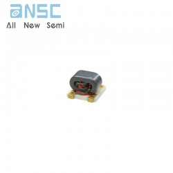
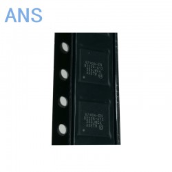
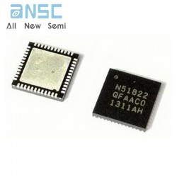
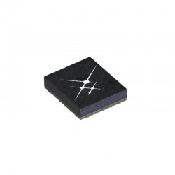
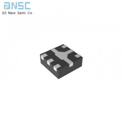
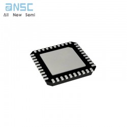
Image shown is a representation only.
Exact specifications should be obtained from the product data sheet.
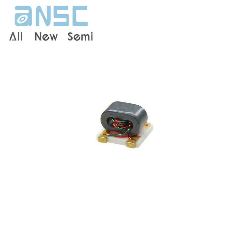
TC4-1TG2+ Dual Path Low band RF Receiver 400 MHz to 1100 MHz SMD
This document describes the specifications for the F1130 Dual Path RF Receiver consisting of RF amplifier with bypass, DSA, RF Mixer & IF amplifier in each signal path. Applications include Multi-mode, Multicarrier BaseStation Receivers. F1130 supports the following frequencies: RF from 400 MHz to 1100 MHz, LO from 500 MHz to 1300 MHz, and IF from 25 MHz to 400 MHz. Refer to the Part # Matrix below describing the complete series.
The F1130 RF front-end offers 19 dB gain with 3.5 dB NF and +37 dBm OIP3 performance. The digital step attenuator provides 30 dB adjustment range in 2 dB steps via the SPI interface controller. For strong signal conditions, each RF amplifier can be bypass controlled via the SPI interface. The RF front-end output and mixer input signals are bonded to separate pins to allow interstage image-reject filtering.
Each of the dual mixer paths provide 9 dB power gain, 10.3 dB NF and +36 dBm OIP3 performance. An external LO signal is applied to the mixer LO port.
This device is packaged in a 7mm x 7mm, 48-pin Thin QFN with 50 ohm single-ended RF & LO inputs and 200 ohm differential IF output impedance for ease of integration into the receiver lineup.
• Dual Path for Diversity / MIMO
• Glitch-FreeTM Technology
• RF: 400 MHz to 1100 MHz
• LO: 500 MHz to 1300 MHz
• IF: 25 MHz to 400 MHz
• Bypassable RF amplifiers for strong signal conditions
• 19 dB RF front-end power gain
• +37 dBm RF front-end OIP3 (Bypass OFF)
• +43 dBm RF front-end OIP3 (Bypass ON)
• 3.5 dB front-end NF AT 900 MHz
• 9 dB mixer power gain (HS LO)
• +36 dBm mixer OIP3
• 50 Ω RF & LO impedance
• 200 Ω differential IF output impedance
• Independent CHA, CHB path standby mode
• 30 dB gain control range, 2dB steps
• 3 bit SPI control
• Total ICC = 360 mA
• 7mm x 7mm, 48-pin TQFN package
| Attribute | Attribute value |
| ANSM-Part# | ANSM-TC4-1TG2+ |
| Category | RF and Wireless |
| Balun | |
| Manufacturer | - |
| Series | - |
| Packaging | Tape & Reel (TR) |
| Cut Tape (CT) | |
| Digi-Reel® | |
| Part Status | Active |
| Frequency Range | 50MHz ~ 1GHz |
| Impedance - Unbalanced/Balanced | 1:4 |
| Phase Difference | - |
| Insertion Loss (Max) | 2.0dB |
| Return Loss (Min) | 14.29dB |
| Package / Case | 5-SMD Module |
| Mounting Type | Surface Mount |
For more product information, please download the PDF
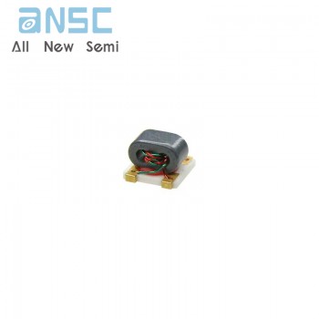
TC4-1TG2+ Dual Path Low band RF Receiver 400 MHz to 1100 MHz SMD
SEND
RFQ